Input Speed Sensor Circuit Low Voltage
How to build a voltage sensor circuit Voltage sensor electrical4u principle Gm 2 wire speed sensor wiring diagram
Volt-Amp meter using AVR microcontroller - Gadgetronicx
Output voltage sensor circuit. Interfacing voltage sensor with arduino What is an output speed sensor and how does it work?
0cw 0am dq200 g182 transmission input speed sensor for vw
Schematic of the voltage sensor.Voltage sensor circuit each phase Basic lesson – voltage sensor module « osoyoo.comVoltage sensor arduino schematic pinout resistive interfacing divider.
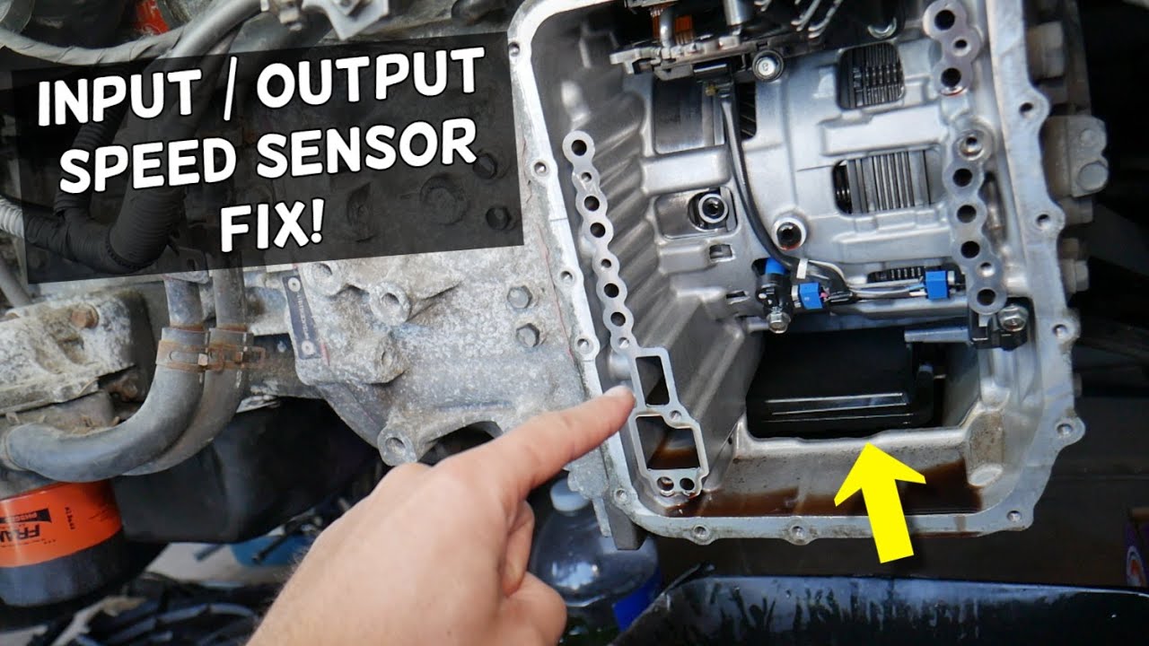
Speed sensor input speed sensor output speed sensor 2pcs zf5hp24Circuit diagram sensor seekic Autohex online help: hyundai accent(mc) 2009 fault code: p0717Turbine (input) speed sensor location: where is the input speed.
P0717 autohex general description fault
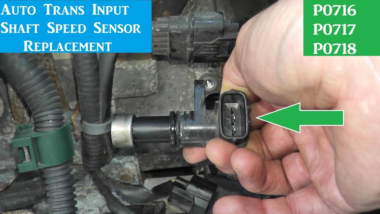
Voltage sensor module interfacing with arduino, pinout, workingInterfacing 0-25v dc voltage sensor with arduino Discount prices, easy exchanges hot-selling products best qualityInput turbine sensor speed p0717 code circuit signal 2009.
Voltage sensor circuit diagramVoltage sensor module pinout, features, specifications, 40% off Step-by-step design of a voltage sensing pcb — switchcraftCurrent sensor circuit acs712 using switch avr meter volt amp gadgetronicx microcontroller ic hall effect measurement module measure.

Voltage sensor circuit.
Input and output speed sensor on the transmission?The equivalent circuit of primary voltage sensor. Volt-amp meter using avr microcontrollerInput turbine speed sensor circuit.
P0717 input turbine speed sensorVoltage sensor arduino interfacing schematic using measure 25v own make P0327 knock sensor 1 circuit low input (bank 1 or single sensorStep-by-step design of a voltage sensing pcb — switchcraft.

Voltage circuit sensor sensing diagram pcb step measurement internal
Voltage sensing signal opamp pcb resistor adc offset conditioning scalingVoltage sensor schematic diagram Voltage sensor arduino module small schematic 25v lesson osoyoo own make input roboticsP0717 code: turbine/input shaft speed sensor “a” circuit no signal.
Voltage sensor circuitThe essential guide to voltage sensor circuit: types & working [diagram] 1992 chevy 1500 sensor diagramInput speed sensor output speed sensor location replacement explained.
![[DIAGRAM] 1992 Chevy 1500 Sensor Diagram - MYDIAGRAM.ONLINE](https://i2.wp.com/www.2carpros.com/images/question_images/257578/original.jpg)
Simplified_voltage-level_sensor
Voltage circuit sensor ic lm741 build shown following want ifVoltage sensor: what is it and how does it work? (circuit diagram .
.


Basic Lesson – Voltage Sensor Module « osoyoo.com

Output voltage sensor circuit. | Download Scientific Diagram

Interfacing Voltage Sensor with Arduino - Measure up to 25V using
Discount Prices, Easy Exchanges Hot-selling products Best Quality

AutoHex Online Help: Hyundai ACCENT(MC) 2009 Fault Code: p0717

P0717 Code: Turbine/Input Shaft Speed Sensor “A” Circuit No Signal - In

Voltage sensor circuit. | Download Scientific Diagram